

For those of you that have ever designed a layout yourself, you’ll know that a model railway reverse loop can be a handy tool in reversing locomotives. Reverse loops allow a locomotive or train to drive from one section, round the loop, and finish on the same section that they started on, but facing in the other direction.
Other examples are ‘triangles’, where a reversing operation is achieved by moving the locomotive or train around a section of track in the shape of a triangle.
Many of the real railways that use the reverse loop technique are powered by a ‘third rail’ - this could be a physical third rail or overhead catenary, for example. This makes things easy, as the power flowing through the two running rails is the same. For many model railways, (with the exception of those using Marklin track, which utilises a 3-rail system), the outer rails are opposing polarity.
When a reverse loop, or triangle (as we will see later), is installed, a rail with a positive polarity will end up joining to a rail with negative polarity, which results in a short circuit. Regardless of the type of control, whether analogue or digital, the same problem exists. If we think about it in terms of analogue control, the following happens:
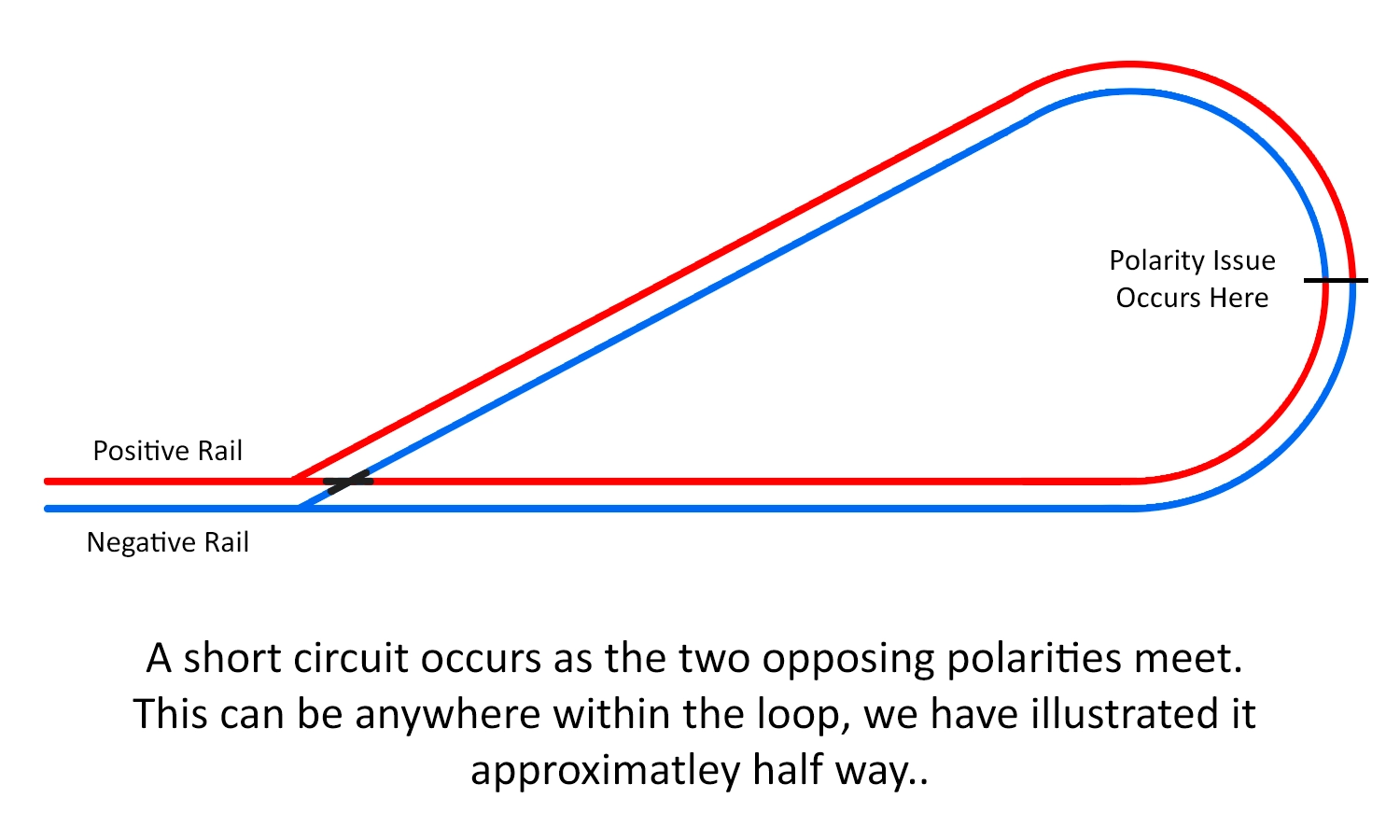
This image demonstrates the short circuit issue when the polarity collides
The solution to the problem differs depending on whether you are using analogue or digital control, but the basis is the same. Regardless of your control type, the first aim is to stop the short happening. The easiest way to do this is to create a gap in the rails. This can be done by either:
Regardless of the method above, this needs to be done on both rails at the same position.
This has now stopped the issue of the controller tripping. However, the short will still exist when a locomotive wheel, or any metal wheel from an item of rolling stock, bridges the gap. The solution to this is to create a completely isolated section. This is done by adding a second insulated break further along in your model railway reverse loop. This isolated section needs to be slightly longer than your longest-powered unit. In many instances, this only needs to be the length of your longest locomotive, but if you’re running multiple units, the gap needs to be longer than the distance between the first and last powered axle.
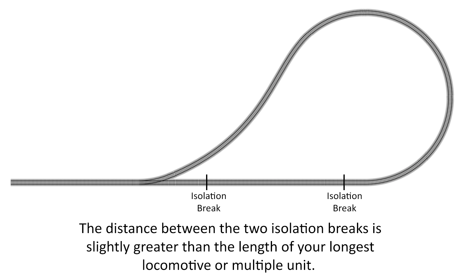
An example of where the isolated section could be located
Once this is installed, we just need to power this section. This is where the solution differs for analogue and digital users.
Now that we have our isolated section, we need to power it to allow the trains and locomotives to pass through. Using no more than some layout wire and a DPDT switch, a solution can be installed. The DPDT or 'Double Pole Double Throw' switch will be responsible for changing the polarity in the isolated section. The wiring for this is shown in the following diagram.
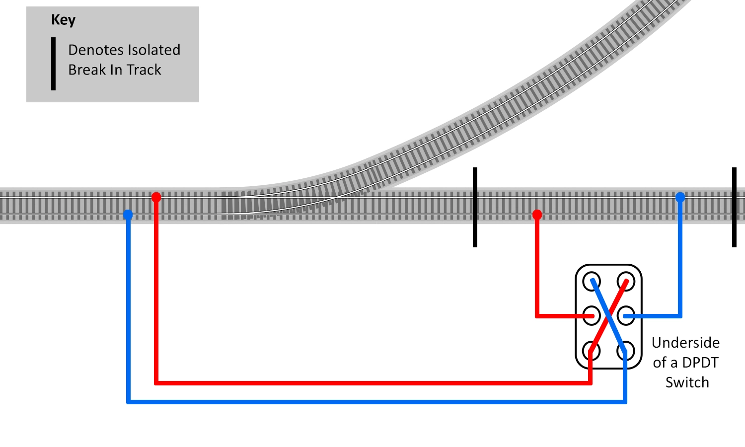
How to wire a DPDT Switch to control the isolated section
Please keep an eye on the colour of the wire used in the diagram to make sure you connect the wires to the correct points. The top and bottom terminals of the switch are connected, but in opposite directions. This creates the changeover as required.
Once this is installed, your model railway reverse loop is wired up and ready to go. All you need to do to operate is simply drive your locomotive or train around the loop and stop it in the isolated section. Stop the locomotive and flick the DPDT switch. You can now continue to drive the locomotive or train away.
This will work for any analogue layout, with or without a point motor installed on the point. If you do have a point motor installed, you can wire up the reverse loop to change the polarity with the throw of the point motor. To do this, you will also require a GM500 Universal Relay Switch. This takes the place of the switch and wires up in a similar way, as shown below.
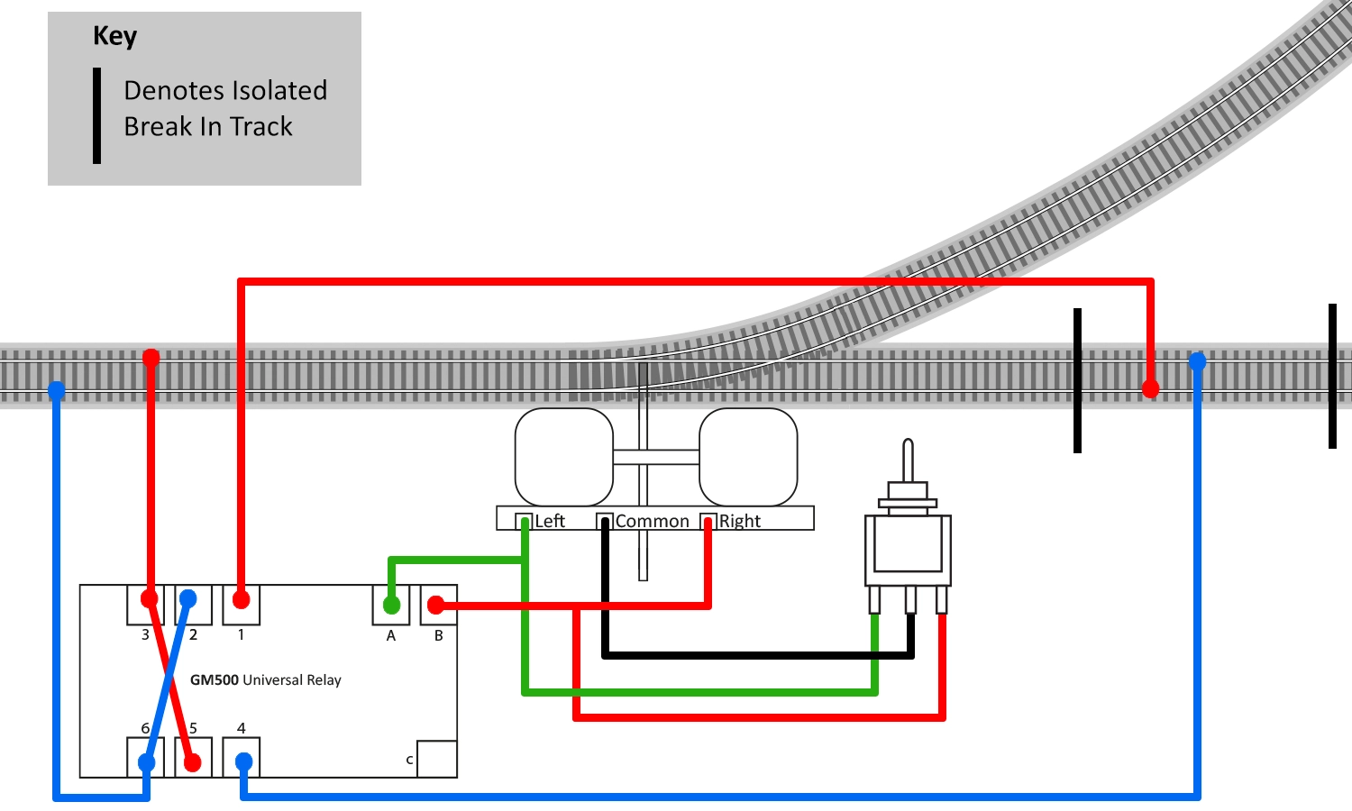
Here we see the wiring for the GM500 Switch. This ties in with the control of the point.
Once installed, it will work in the same way as using the switch, except this time you only need to throw one switch to change the motor and the polarity. Note that you will need to stop the locomotive in the section prior to switching the point over, otherwise, your locomotive or train will short out your controller.
When installed, you may find that the unit is reversing the polarity in the opposite way to that required. If this is the case, simply swap the two wires that are connected to the GM500 on terminals 1 and 4, and you’ll be away.
As previously explained; a reverse loop on any layout will cause a short when connected up as opposing rails connect. This may not seem like an issue when using DCC (Digital Command Control), as it operates on an alternating current, but in reality, it’s exactly the same problem as with analogue layouts.
Analogue layouts use a constant positive and negative feed on the rails, which are reversed with the controller switch. Digital uses an alternating feed on both rails simultaneously; however, each rail is oscillating in the reverse of the other. Essentially, they are constantly switching between positive and negative and negative and positive.
For an analogue model railway reverse loop, we would use a switch to change the polarity, but with DCC, we have the benefit of digital technology. The connections to the track are the same as with analogue, with the difference of an auto reverse module being installed instead of the DPDT switch.
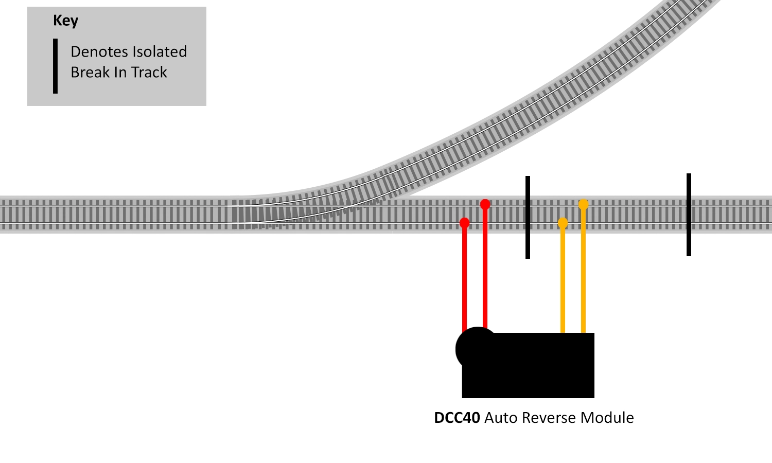
Caption: Wiring for the DCC40 Auto Reverse Module
Auto reverse modules do exactly as their name suggests - they automatically reverse the polarity of the reverse loop. This is done as the unit detects the short when a wheel bridges the isolated gap. This causes the unit to activate and switch the polarity in the isolated section to match, correcting the short.
This process is repeated when the wheel leaves the section, causing the second short. Because the unit activates on detecting the short, for DCC users there is no need to stop the locomotive or train in the isolated section. Once installed, welcome to the world of automatic polarity change on your DCC reverse loops!
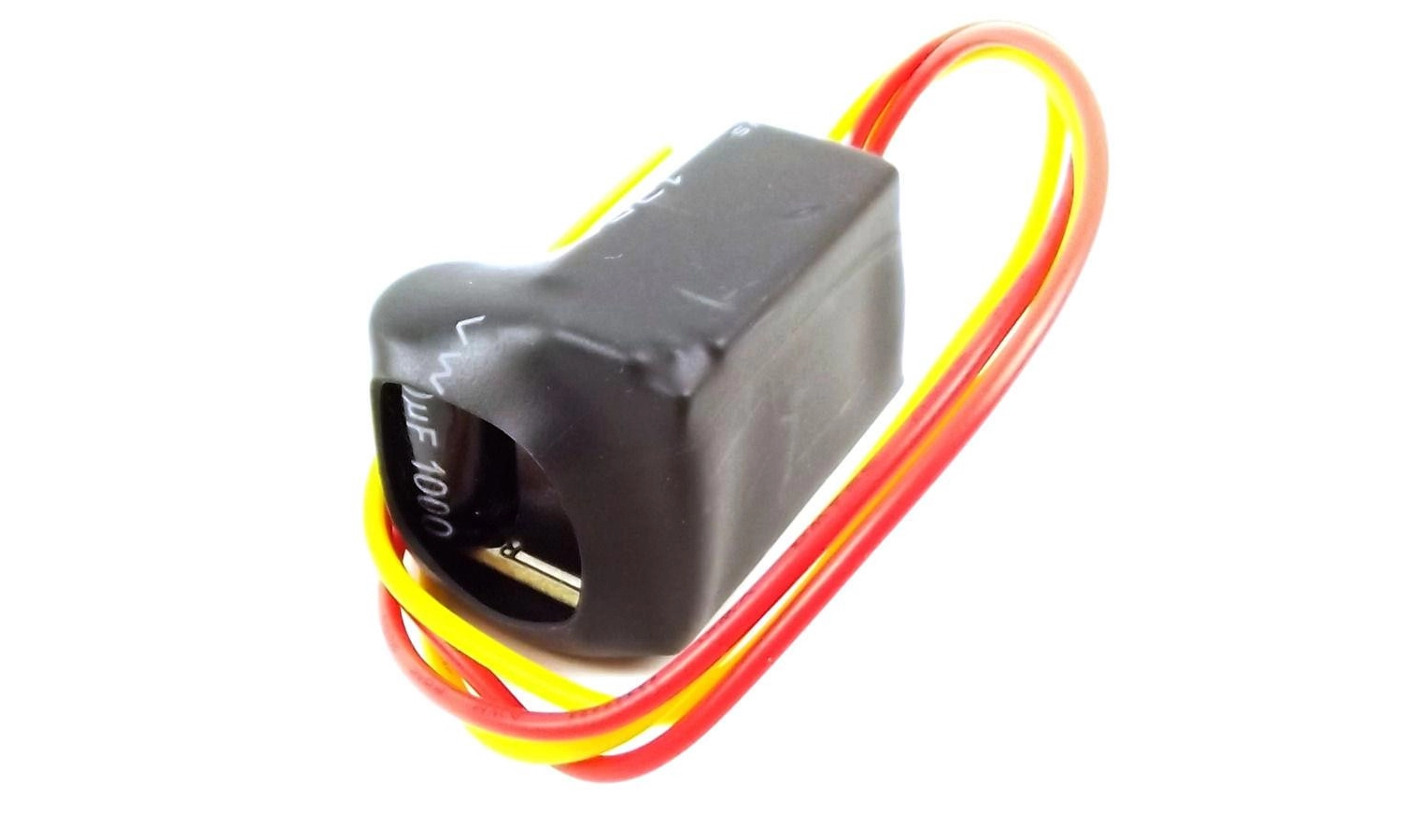
The Gaugemaster DCC40 Reverse Loop Module
The Gaugemaster DCC40 Auto Reverse Module is designed and built to NMRA standards and will work with the majority of digital controllers. It is unfortunate, however, that because of the design of some of the more basic systems, it does not work with all of them. There are many factors that can affect a model railway reverse loop module, and our advice would be to always use one that’s produced by the same manufacturer that makes the controller you are using, as they will have to check it works with their system. If in doubt, always consult the manufacturer.
There are some situations where model railway reverse loops can become more complicated or be embedded within a layout. We’re often asked about double reverse loops, where two overlap. An image of this situation can be seen below.
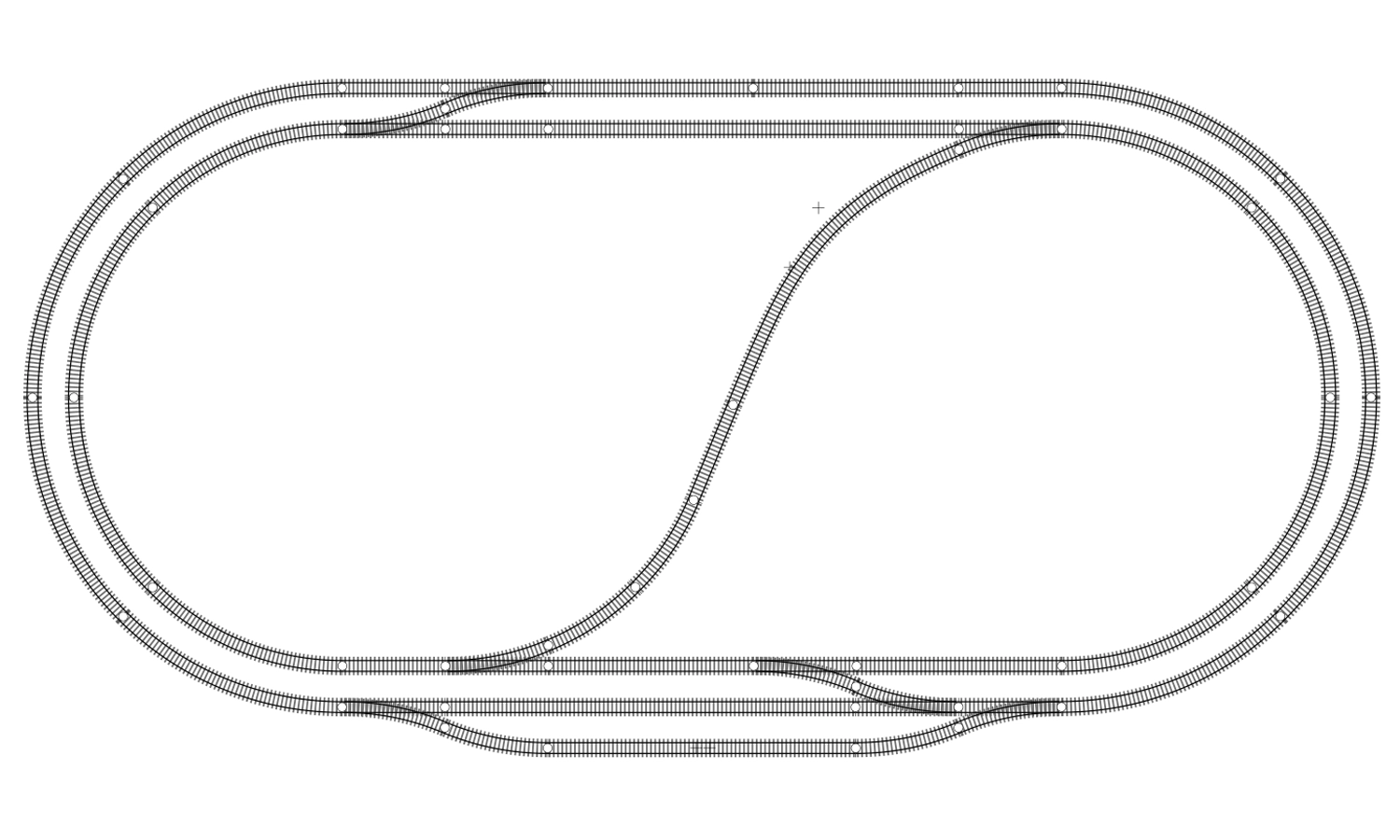
A common example of a layout featuring a double reverse loop.
This illustrates a very common track arrangement in which the modeller uses the central track to connect the top and the bottom of the layout. This could be intentionally installed as a reverse loop, but it does appear in many track plans to give more interest and use of the centre of the layout. The reason we refer to this as a double reverse loop is that it creates two reverse loops connected via a common section, which if not present, would mean no reverse loops were created.
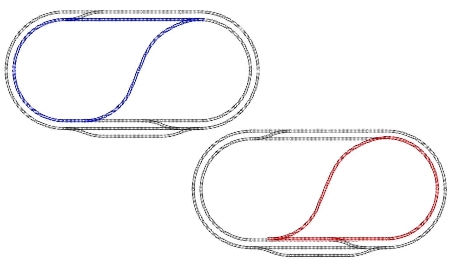
The locations of both the reverse loops.
The key to solving this problem is actually quite simple. Because the two model railway reverse loops share a common section of track, only one isolated section is needed. Once this is realised, the wiring becomes as straightforward as for a standard reverse loop scenario.
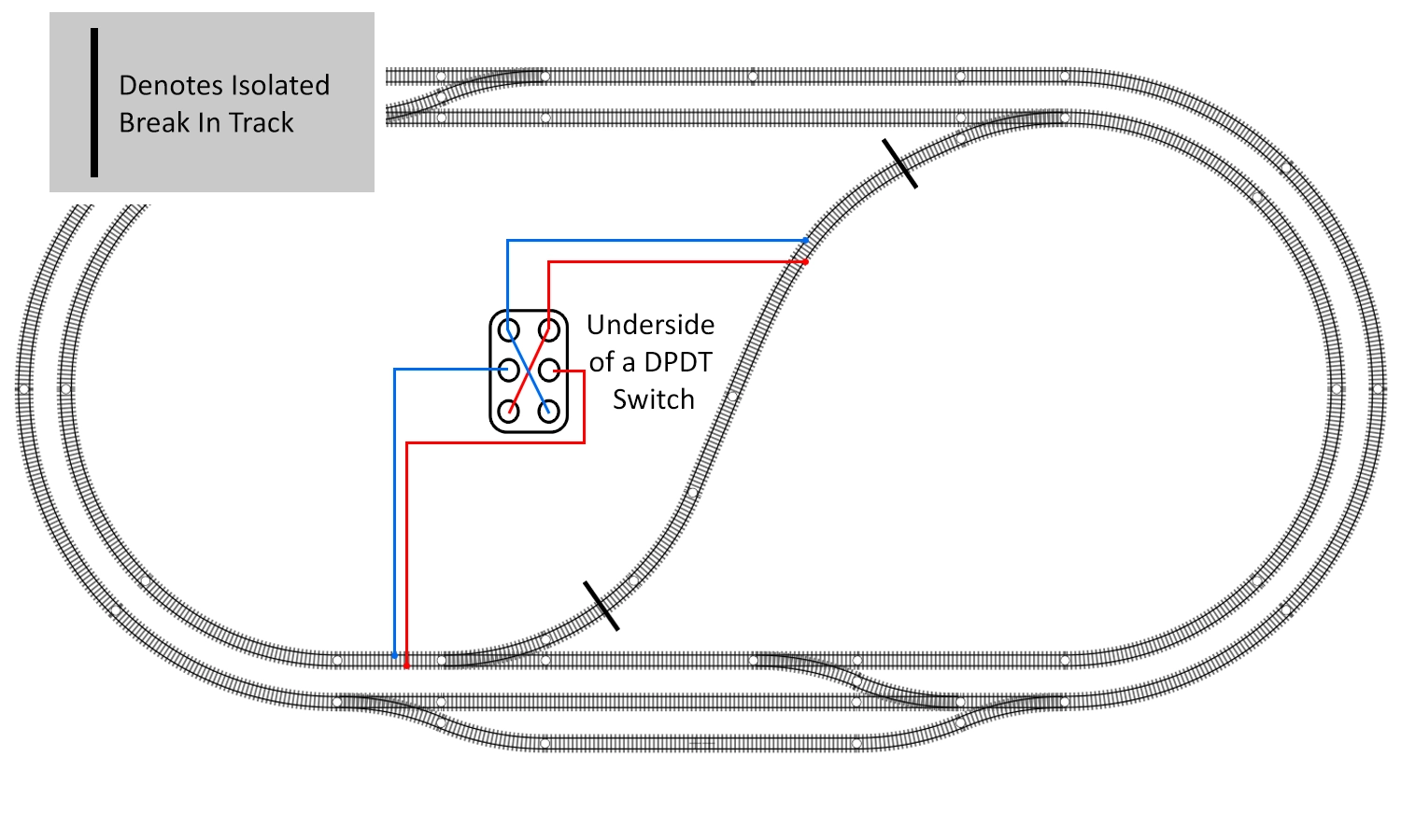
The analogue wiring of a double reverse loop.

The digital wiring of a double reverse loop.
A triangle is also a type of model railway reverse loop. Although there is no ‘loop’, the problem still exists in the same way, and for the same reasons. There aren't many model railway layouts that include a triangle, possibly due to people thinking they are going to be a nightmare to wire, or the fact that they can take up a larger space than simpler formations. Regardless of the reason behind it, you may want one on your layout.
A real-world example of a triangle can be found a few yards down the line from Gaugemaster HQ next to Ford station. This triangle connects the up and down lines from Littlehampton, Barnham, and Arundel. There is also an offshoot to Brighton just after the points, allowing the Arun Valley line connection to the triangle, making this a very interesting junction.
A Google Maps Image of the Arundel/Ford/Littlehampton Junction. The Branch leading to the right splits into Brighton Mainline and the Arun Valley line to Horsham and London.
Even in recent years, this triangle has been used for turning trains. A steam special was run from Portsmouth to Littlehampton, before being run in reverse around the triangle to Arundel. The train was then brought down from Arundel in the correct orientation, allowing it to return to Portsmouth without the need of the locomotives running round the train - something that’s not possible with other track formations.
To explain the situation of the reverse loop, we need to consider where it forms. In basic terms, when you have the three points connected in a line without the third side of a triangle being connected, you don't have a problem with a reverse loop - it simply appears as two sidings with a head-shunt on each.
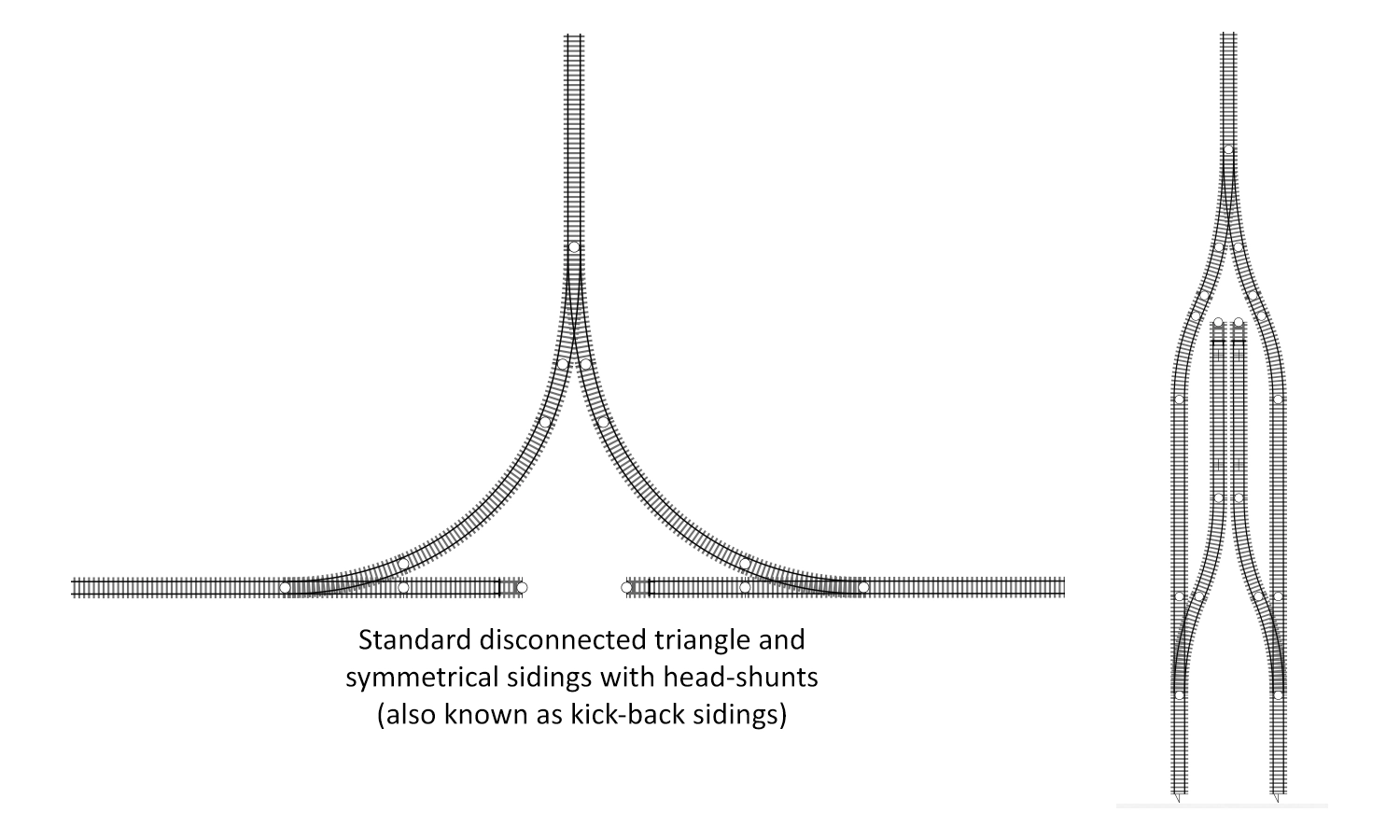
An example of a similar situation that is not a complete triangle.
This specific model railway reverse loop problem appears when you add the connecting section.
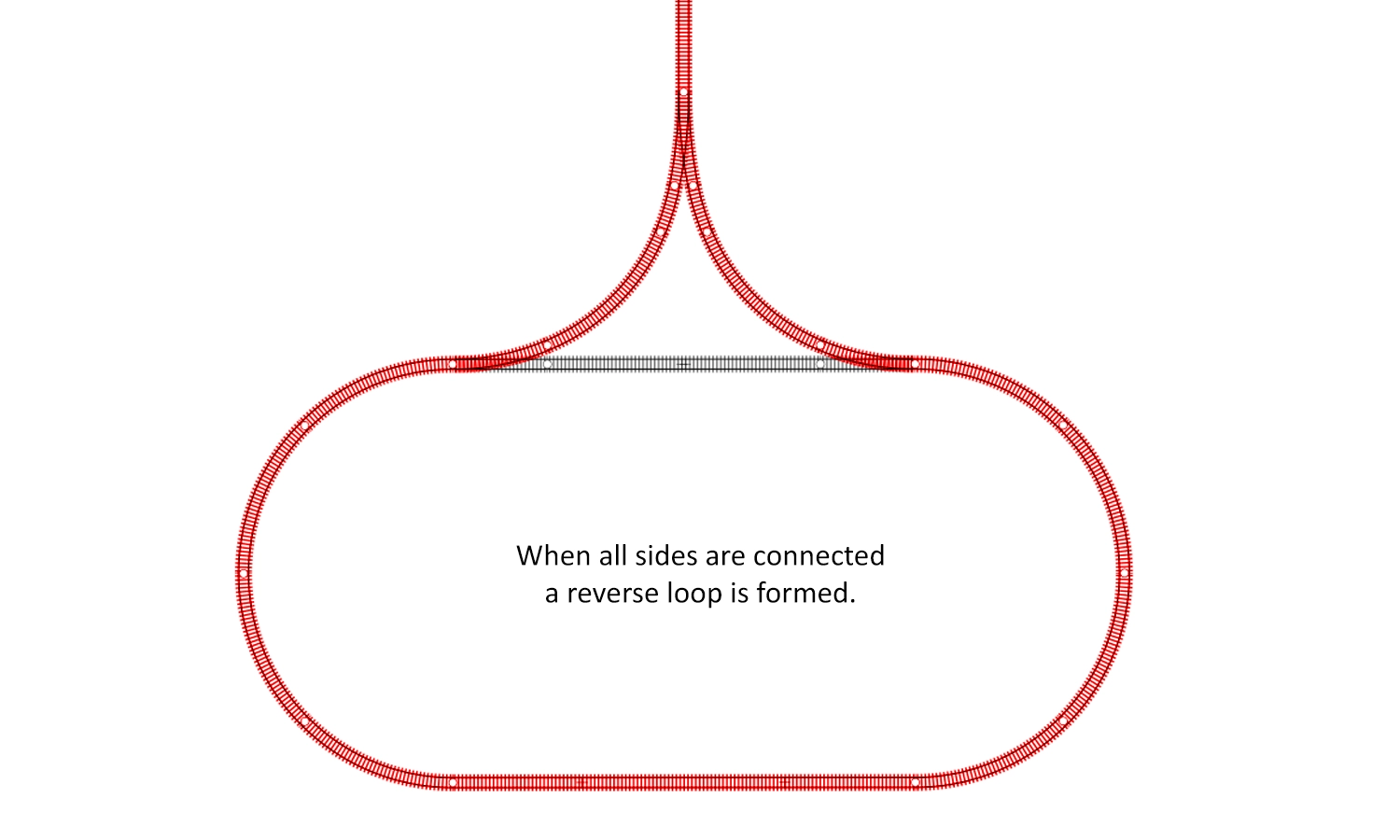
Here we see the polarity issue when the third side of the triangle is added
You’ll notice that the connecting section does not form part of the reverse loop. However, you would still require feeds at each end of the ‘points’ of the triangle, which electrically creates the same loop. So regardless of the track being present creating the loop or just the wiring, the polarity issue still occurs.
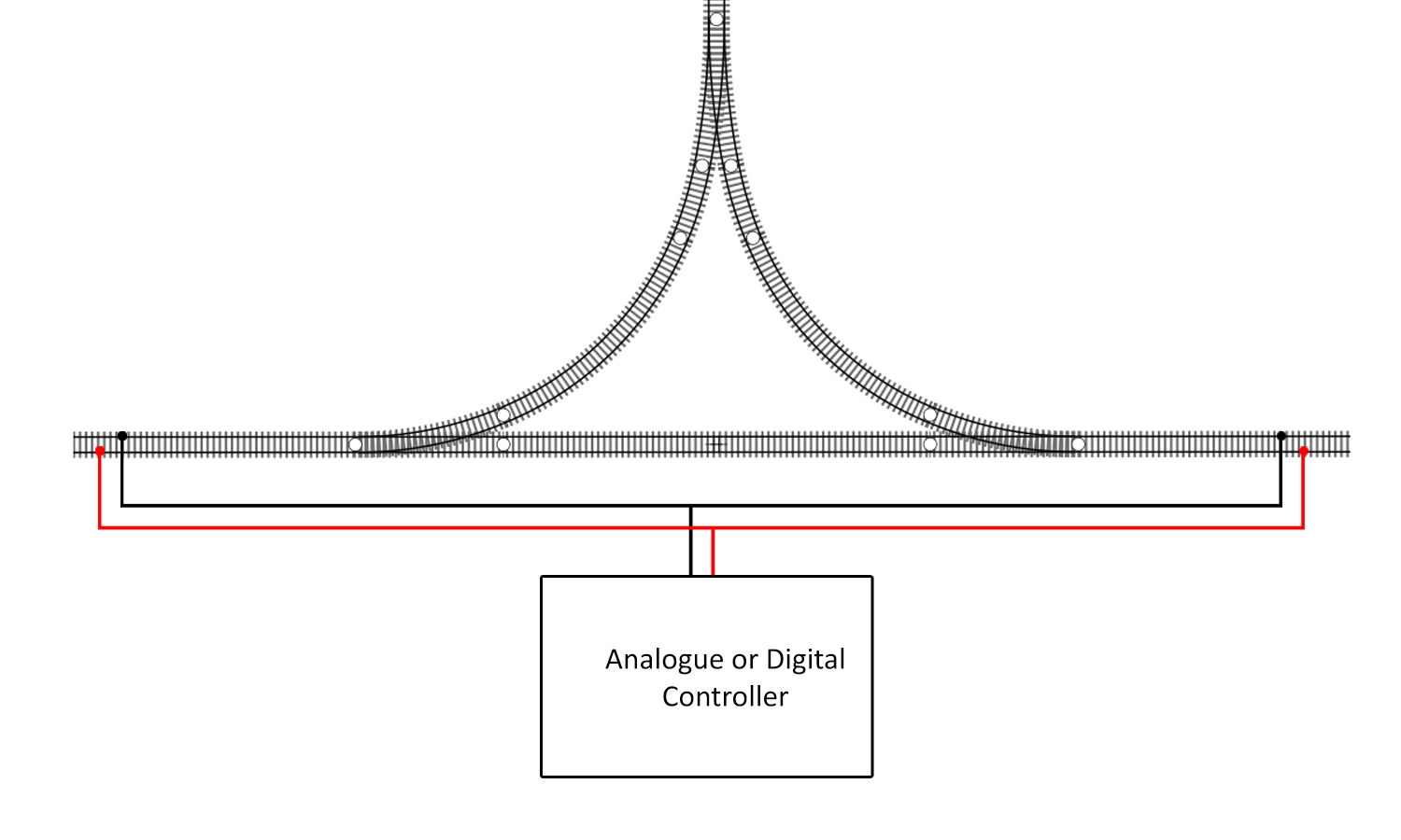
This diagram illustrates the wiring creating the ‘reverse loop’
Once this issue is realised, we can look at the problem in regards to a reverse loop. Just as before with the standard and double reverse loops, the wiring is the same. Simply isolate one side of the triangle, as if it was the isolated section on a reverse loop, and wire either your switch or auto reverse module as before.
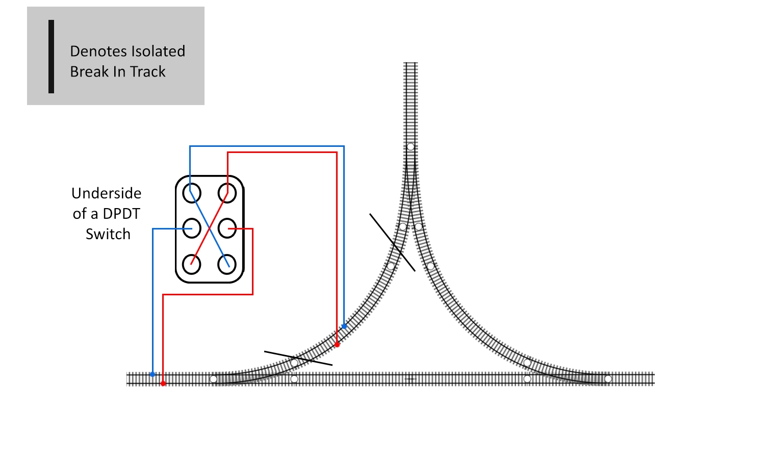
The wiring and isolation position of a triangle on an analogue controlled layout.
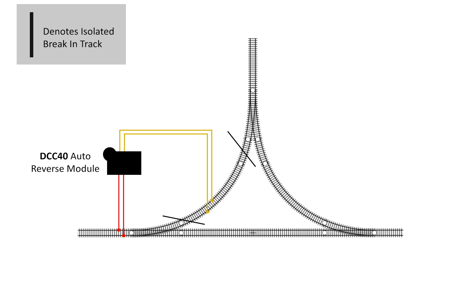
The wiring and isolation position of a triangle on a digitally controlled layout.
From here, you’ll be ready to go. The only word of warning is that triangles tend to be more compact than a reverse loop. This means that there is a limited space in which you can isolate, so there’ll be a maximum length of train or locomotive. If you need a longer isolated section as discussed previously, then you may need to consider widening your triangle.
Turntables are a strange phenomenon on model railway layouts. They tend to be used for either accessing sheds or turning steam locomotives. With the invention and spread of diesel locomotives with cabs at both ends, both requirements faded out and turntables were removed. Many modellers do find the inclusion of a turntable an extra bit of fun and tend to ignore the prototypical uses of them. We don’t mind this at all - in fact, we’ve done the same on our Kato display in our shop.
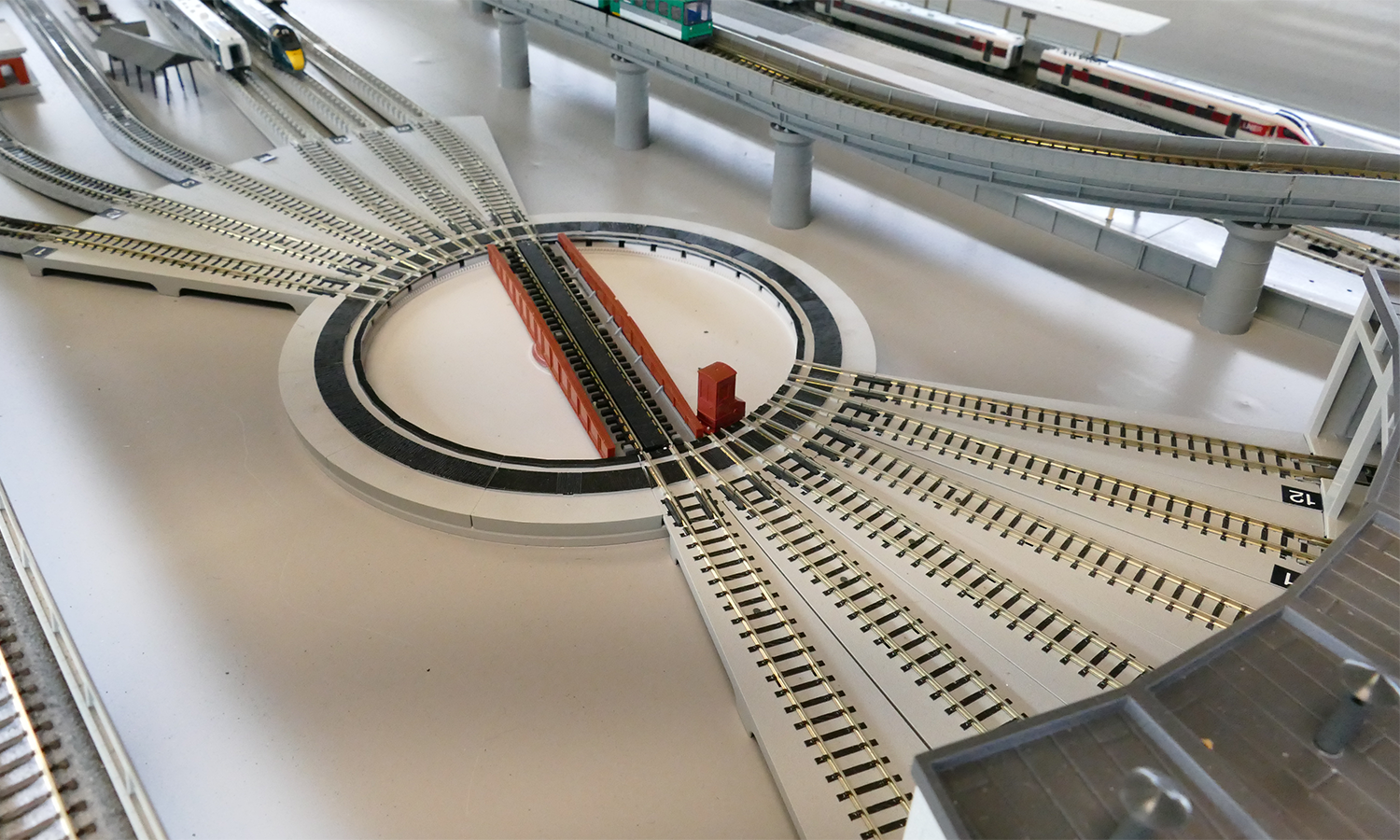
The location of this turntable is less than prototypical, but adds a fun element and extra storage to the layout
So why are we featuring turntables here? Well, the issue of opposing polarities can be found here too. When turning the turntable up to 179°, no polarity issues occur. Once you pass this and do a full half-rotation, then you’ll experience the same issues.
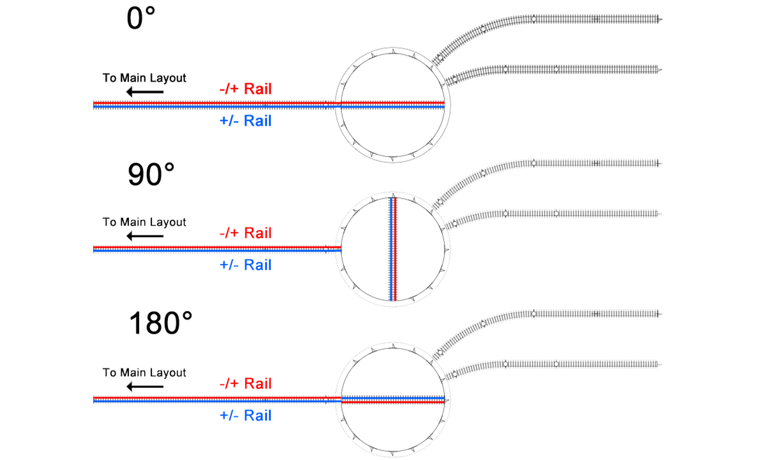
We can see here the point where the polarity issue occurs.
Although this could be a tricky thing to overcome, the wiring is actually very similar to that of the reverse loop. In this instance, the bed (the rotating platform) of the turntable becomes the isolated section. Depending on the turntable, you may need to isolate all the output rails on the turntable or just after. Check with the manufacturer or instructions for the turntable prior to installation. Once these and the rails leading into the turntable have been isolated, the wiring is the same as that of the reverse loops.
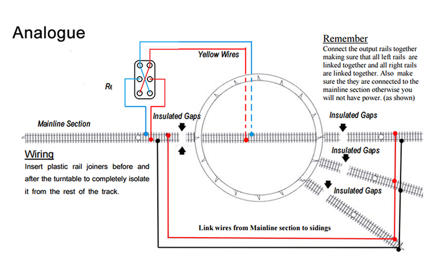
The wiring and isolation position of a turntable on an analogue-controlled layout.
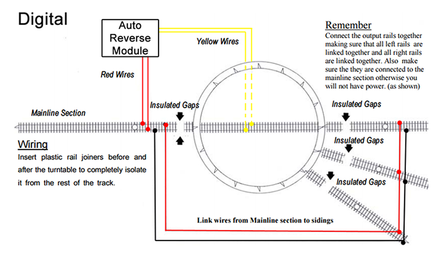
The wiring and isolation position of a turntable on a digitally controlled layout.
This will get you up and running with your turntable, and stop shorting when the turntable goes past the 179° mark. If you’re using the above to wire a turntable on an analogue set-up and want to store locomotives on the output tracks, you’ll need to wire a switch into the wires feeding the section.
When wiring this up with analogue, if you want to store locomotives in the sidings for any length of time, take separate feeds to each line through an on/off switch. And there you have it - everything you need to know about dealing with model railway reverse loops for both analogue and digital set-ups!
Further Reading
You may also find the followinf articles of interest:
Foot Notes:
Map Data © 2023 Google
This article has been written by our staff here at Gaugemaster, drawing on thousands of hours of modelling experience. Each article has been written to make it easy for everyone from beginner to expert to learn and expand their own knowledge base. If there is something you would like to see covered, feel free to contact us to suggest a topic - we’d love to hear from you.
For more articles like this, and many others; don't forget to check out the Gaugemaster Knowledge Base.